
To get the most out of your GSM repeater, it is important to find the best possible signal outdoors. In fact, there is nothing "magic" about a GSM amplifier: the GSM amplifier can "only" amplify existing waves and not recreate them from scratch. Also, the better the signal received, the better the performance of your GSM amplifier. It is your kit's external antenna that comes "first," so it is important to do a careful installation. There is nothing complicated to do, you just need to pay attention to a few steps, which are described below. Reading these steps in a few minutes (about 3 minutes) will save you a lot of time during installation!
- First do a test installation!
- Find the optimal outdoor signal
- Find the nearest transmission towers
- Ensure optimal distance between antennas
- Principle of self-oscillation (loop through antennas)
- Remote loop solutions
- Loop solution by mass action
- Other possible solutions
- Mount and align the outdoor antenna correctly
1. First do a test installation!
This is THE secret to proper installation of your GSM amplifier: do a test installation first! After that there will be time to secure the attachment points firmly and hide the cables.
Mount the antennas but secure them provisionally, with the coaxial cables not yet in their final position.
Connect all elements and turn on your GSM amplifier to see if everything is working normally. - Is everything working properly, no feedback? Then the location of the indoor and outdoor antennas is ldeal. Now you can turn off the GSM amplifier, connect the antennas firmly and install the cables. And it is done!-
Is there feedback or is the signal not well received? then you need to find a better position for the antenna. It is very easy and quick to change the position of the antenna(s) based on the external signal test, repeat this test until you find the right position. This is much easier than having to disassemble and reassemble the whole system again....
2. Find the optimal outdoor signal
With your smartphone you can measure the signal strength outside: you can refer to the bars on the screen or you can see the exact signal strength, expressed in dBm. We prefer this second option. Read more about this on our website.
By the way, since it is a negative value, the best signal is given by the smallest number, which is close to zero, in dBm. For example: -46 dBm is much better than -102 dBm.
For example, try testing different positions from A to E as shown below and choose the best one to install the outdoor antenna: the position with 5 bars (or the best value in dBm).
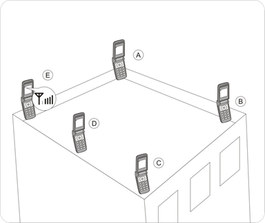
You can use several procedures to test the signal strength in dBm on your cell phone:
For iPhone: open the phone app and type *3001#12345#* as if you were dialing a phone number. Then press the call button. It will open the so-called -menu Field Test field, where instead of the receive bars you will see a negative number (in Dbm) that is much more meaningful.
For Android: download the Netmonitor Cell Signal Logging app. It measures signal type and strength and determines which broadcast tower you are connected to.
3. Find the nearest transmission towers
The outdoor antenna must be aligned with the transmission tower(s). For this we need to know the location of such towers. Ideally, the cell towers are in a direct "field of view," that is, there are no obstacles between the transmission towers and the outdoor antenna.
A directional antenna is usually used in rural areas. It must be made sure that the signal (waves) does not pass through trees and hit buildings or obstacles. The broadcast tower must be "in view" with this type of antenna.
In urban areas where there are more and more broadcast towers, a panel antenna is generally preferred to a directional antenna. Because the outdoor antenna can receive signals over a larger area, it is easier to direct it, but it is still important to point the main surface toward the strongest signal received.
There are multiple ways to locate the positions of the towers:
Each country's Federal Network Agency has posted the locations of cellular towers online. The most "comprehensive," in each case, you can find below. Just click on the link below and locate the address of the facility-the various cell towers in the vicinity will appear on a readable map.
4. Ensure optimal distance between antennas
Because of the nature of a repeater, it is important to prevent the antennas from tapping each other otherwise your system will not work properly or at all.
A GSM amplifier is a system that receives, amplifies, and retransmits.
Each antenna (both indoor and outdoor) acts alternately as transmitter and receiver. If the antennas are too close together, the situation is similar to feedback in a sound system: the sound is amplified by the microphone, then sent to the speaker and picked up again by the microphone, and so on. A loud whistle will be heard and eventually the equipment will break down!
With GSM amplifiers we talk about self-oscillation instead of feedback, but it is the same principle, with the same consequences: whistling and possible destruction of the amplifier.
Your amplifier has automatic settings that allow you to automatically adjust the gain. You can also change the gain manually, but this means that the performance of your amplifier will be greatly reduced or even zero.
Take the example of feedback from a sound system: when it "whistles," you can always turn the volume down to stop the whistling. But after a while, if you turn the volume down too much-there is no sound for your audience! So the solution is to increase the distance between the microphone and the speakers to avoid the looping phenomenon.
The same applies to a GSM amplifier: the antennas must be well insulated.
4.1 Principle of self-oscillation (loop through antennas)
When your antennas "connect" to each other, your amplifier will no longer be able to function properly. At best, it will go into self-protection mode until the amplifier is restarted. At worst, however, the GSM amplifier will be destroyed. Here is the explanation of this phenomenon called self-oscillation:

As shown above, the amplifier amplifies the downlink signal (r) from the transmission tower and sends the signal to the amplifier. Then the amplified signal (R) is sent to the indoor antennas. If the distance between the two antennas (outdoor antenna and indoor antenna) is insufficient, the amplified signal (R) is also sent to the cell phone from the outdoor antenna as indicated by the red dashed lines in the drawing. The same applies to the signal (t) from the uplink to the antenna: the amplified signal (T) is again received by the indoor antenna.
This can be avoided by following the following two suggestions, individually or cumulatively. This is known as antenna isolation.
4.2 Remote loop solutions
Move the antennas as far apart (from each other) as possible. A distance of 10 meters between antennas is generally considered sufficient protection against interference. Each kit comes standard with a 10-meter coaxial cable, so make the most of it. If you need a longer length, you can find all our coaxial cables on this page.
You may have used the full length of the cable, but the point-to-point distance between antennas may be only 3 or 4 meters (due to corners and edges, ceiling drop, etc.). Typically, especially in the case of an installation with multiple indoor antennas, natural oscillation usually comes from the indoor antenna closest to the outdoor antenna.
In this type of configuration, it is to this antenna that we want to draw attention; the second solution (ground effect; see below) can be used in combination with this solution to stop the natural oscillation.
Sometimes the distance is right, but the interference remains. Check for windows, awnings, wood panels, grates or any other surface or opening that is "permeable" to the waves and allows the signal to enter the room; sometimes it turns out to be very simple. This is where the second solution to vibration comes in: the ground effect.
4.3 Loop solution by mass action
Any material that is poorly permeable or impermeable to waves is called a "mass." Examples include: metal panels (e.g., hangars), concrete walls or ceilings (with metal in them), very thick old walls, a lead sheet, metal grates or grids connected to the floor ... generally provide a good mass effect.
Thus, the "ground effect" offers an opportunity to take advantage of the presence of certain materials that lie between the outdoor antenna and the nearest indoor antenna. The idea is to wirelessly separate your antennas so that waves are attenuated or blocked by obstacles between your antennas, or in other words, so that the isolation between the antennas is sufficient to prevent self-oscillation.
4.4 Other possible solutions
The above two solutions (distance and ground effect) can be perfectly combined to achieve the best possible isolation of the antennas and thus neutralize self-oscillation. This combination is recommended as much as possible, depending on the possibilities offered by the location to be set up.
Some examples for better understanding:
- Only 7 meters distance between outdoor and indoor antennas, but also 2 bearing walls between antennas.
In that case, self-oscillation is very unlikely. - Antennas on the same floor (outdoor antenna directly above a window), but 10 meters apart, with 2 doors in between: self-oscillation is unlikely, but possible because of the doors (e.g., if they are wooden).
Be careful of skylights and other windows, they will pass the signal through and damage the insulation of your antennas.
Extra tip: You can also consider the directivity of the antennas and make sure that none of the antennas are in range of the other antennas. See later in this article for more information on directivity--because the back and sides of the antenna also spread residual waves (even with a very directional antenna!).
Keep this in mind when you test the signal at different points, this parameter will help you a lot.
5. Mount and align the external antenna correctly
Depending on the type of external antenna supplied with the kit, here are some things to keep in mind. It's not very complicated, but "better a little drawing than a long speech...."
5.1 Installation and confirmation
Very easy, because the mounting plate and screws are supplied with the antenna. All you need is a wrench (or a universal clamp).
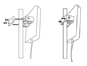
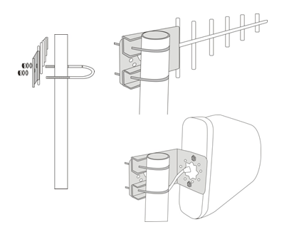
5.2 Guide
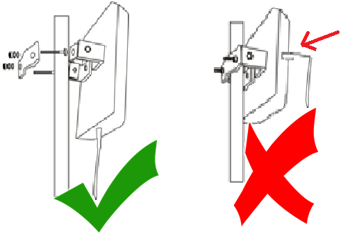
Always make sure that the antenna wire comes out from the bottom (as shown in the drawing) or the top. If the antenna wire comes out to the left or right, the antenna is no longer polarized and will no longer be able to pick up the signal properly.
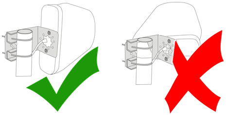
For the directional antenna, the "sides" should be placed as above.
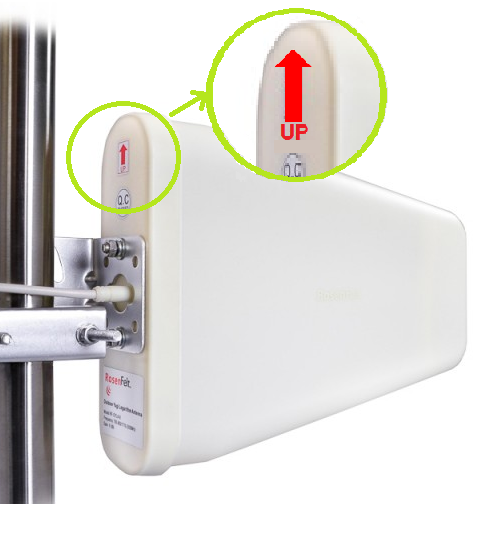
On the directional antenna (Yagi Logarithm or Yagi Super Logarithm) please note the direction of the red arrow on the back for proper drainage: the red arrow should point upward, as shown in the following figure.
5.3 Alignment with the transmission tower
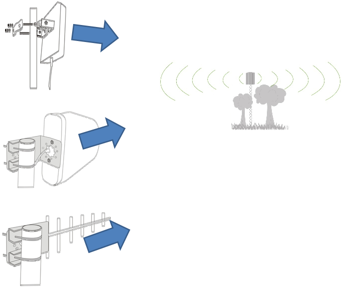
Look at the picture below: the plastic surface of the panel antenna is the "exchange surface" of the antenna itself, through which the waves pass. This part should be positioned toward the nearest broadcast tower, the one that has the strongest signal. With directional (Yagi) antennas, the tip of the "arrow" indicates the direction in which it should point.
5.4 Beware of obstacles
This is especially important for directional Yagi antennas. The tip of your outdoor antenna should point toward the cell tower--ideally, the cell tower should be "in view"!
You may not see it with the naked eye (especially if it is miles away), but you need to make sure there are no obstacles between your outdoor antenna and the broadcast tower: no forest, no mountains, and even less a building or any other structures.
Imagine pointing a laser beam at the cellular tower: can the cellular tower be reached from where you are? In other words, is your directional antenna properly aligned with the tower, in a straight line and unobstructed?
- Then you have done everything right: your directional antenna is in the right place and will receive the best possible signal for your GSM amplifier.
- Otherwise--the signal cannot be received properly by the directional antenna. The solution is to find another free space between you and the directional antenna or consider another type of antenna that is less directional..
5.5 Characteristics of panel antennas
Regarding flat antennas (Panel antennas), as we have seen above, the receiving surface must be aligned with the transmitting towers. Orientation is less critical than a directional antenna, but it is important to always place this panel antenna in the direction of the strongest possible signal.
If you are not sure where the strongest signal is coming from, continue with subsequent tests by rotating the antenna mount (around its mounting axis): aim 90 degrees more each time... until the strongest signal appears on your repeater.
This should make it easy to install the external antenna.
Each type of antenna (omnidirectional, semi-homnidirectional, directional, or ultradirectional antenna) has its advantages and disadvantages-sometimes it is difficult to get your bearings and choose the right option. We offer different types of antennas so that our amplifiers work optimally and respond precisely to the constraints of your location-this way we can respond to each individual case. Just ask us, our team can help you!